To finish and submit the proposal report and blog to the supervisor.
Analysis/Discussion: This is the last week for me to finish up my proposal report and blog because this week is the submission date. The last day to submit is on Friday. This week I need finish up the small parts in the report. The sections left are the
Abstract
Table of Content
Conclusion
Formatting the report
Conclusion:
By Friday,19/12/2014, I should have submitted my proposal report and this blog. Though this maybe the end of FYP I course, but a much harder and difficult course of FYP II is waiting next semester. I should continue my research on the Thermoelectric Device Charger.
Finalize the project proposal before the due date. Analysis/Procedure:
This week I need to finalize my proposal report and the blog. The proposal report is almost 80% finished. But, this week I am a little bit busy with other reports I have only a little time to work on the proposal report. Fortunately, the proposal report is due next week.
Conclusion: The project proposal is finalize to complete.
All the components needed in this project are sold separately. I took the liberty to survey the price of each components available in electronic shops in Kuala Lumpur. Only the thermoelectric generator (TEG) that I buy from website http://espressomilkcooler.com/thermoelectric-teg-power-modules-under-200c/. After days of research, I have enlist the components and instrument. Below is the table of budget:
Table 1: Total estimation budget for this project
Conclusion:
The total budget of this project is quite expensive. In order to complete the project, the budget above is relevant.
To discuss with my supervisor on Monday and attend the presentation the Project Proposal on Wednesday. Analysis/Procedure: During Monday I met my supervisor, Sir Nor Azman to get advices and discussion about project proposal presentation. After the discussion and some advices, I manage to complete slide presentation as the following format:
The Final Year Presentation I (FYP I) took place in the Dewan Gemilang, Unikl British Malaysian Institute (BMI) on 26th of November 2014. The presentation started at 3:00 in the evening. I was assigned to two assessors from the FYP committee whom are lecturers from the Electrical Section. My assessors are Prof. IR. DR. Mohd Khairil Rahmat and Miss Pusparini Dewi Binti Abd Aziz. The first assessor is Prof. IR. DR. Mohd Khairil Rahmat. I presented my proposal project presentation to him. He listened through the presentation until the question and answer (Q&A) session which he asked a few questions. Fortunately, I answered all his question. In the end of the first presentation, he asked me why i must use DC-DC booster converter rather than transformer. He explain that i might have small current to charging a device. Than i explained to him that my objective the output at USB port is 5V,100mA. After that he suggested me to verify the charging time and also verify which range of different temperature give the best output. He also suggested me to compare charging time using DC-DC booster converter and transformer.
The second presentation with Miss Pusparini Dewi Binti Abd Aziz also went well. Again, I successfully answered her question during the Q&A session except for the last question about cold side design. She does suggested me to compare the output that will generate by using DC brushless fan motor with heat sink and liquid coolant heat sink. Conclusion: I successfully managed to attend and present my project proposal. This is a good thing for my project as the presentation went well. The mark from the presentation will be add to the total mark of FYP 1. At the end of the day, there are several suggestion which I will be facing:
Verified the charging time using DC-DC booster converter and transformer.
Verified the best range different temperature which give the best output.
Verified the temperature that will generate by using DC brushless fan motor with heat sink and liquid coolant heat sink at cold side of thermoelectric module.
Objective: To identify and research about the voltage regulator, heat sink and DC brushless fan motor.
Analysis/Procedure: 1. VOLTAGE REGULATOR:
Figure 6: Sample of voltage regulator
A voltage regulator is designed to automatically maintain a constant voltage level. A voltage regulator may be a simple "feed-forward" design or may include negative feedback control loops. It may use an electromechanical mechanism, or electronic components. Depending on the design, it may be used to regulate one or more AC or DC voltages.
Electronic voltage regulators are found in devices such as computer power supplies where they stabilize the DC voltages used by the processor and other elements. In automobile alternators and central power station generator plants, voltage regulators control the output of the plant. In an electric power distribution system, voltage regulators may be installed at a substation or along distribution lines so that all customers receive steady voltage independent of how much power is drawn from the line.
Transistor regulator
In the simplest case a common collector transistor (emitter follower) is used with the base of the regulating transistor connected directly to the voltage reference:
Figure 7: Transistor regulator circuit
A simple transistor regulator will provide a relatively constant output voltage, Uout, for changes in the voltage of the power source, Uin, and for changes in load, RL, provided that Uin exceeds Uout by a sufficient margin, and that the power handling capacity of the transistor is not exceeded.
The output voltage of the stabilizer is equal to the zener diode voltage less the base–emitter voltage of the transistor, UZ − UBE, where UBE is usually about 0.7 V for a silicon transistor, depending on the load current. If the output voltage drops for any external reason, such as an increase in the current drawn by the load (causing a decrease in the Collector-Emitter junction voltage to observe KVL), the transistor's base–emitter voltage (UBE) increases, turning the transistor on further and delivering more current to increase the load voltage again.
Rv provides a bias current for both the zener diode and the transistor. The current in the diode is minimum when the load current is maximum. The circuit designer must choose a minimum voltage that can be tolerated across Rv, bearing in mind that the higher this voltage requirement is, the higher the required input voltage, Uin, and hence the lower the efficiency of the regulator. On the other hand, lower values of Rv lead to higher power dissipation in the diode and to inferior regulator characteristics.
where VR min is the minimum voltage to be maintained across Rv ID min is the minimum current to be maintained through the zener diode IL max is the maximum design load current hFE is the forward current gain of the transistor, ICollector / IBase
For more detail about voltage regulator there is video at down below.
2. HEAT SINK
Figure 8: Sketch of a heat sink in a duct used to calculate the
governing equations from conservation of energy and Newton’s law of
cooling
Heat transfer principle
A heat sink transfers thermal energy from a higher temperature device to a lower temperature fluid medium. The fluid medium is frequently air, but can also be water, refrigerants or oil. If the fluid medium is water, the heat sink is frequently called a cold plate. In thermodynamics a heat sink is a heat reservoir that can absorb an arbitrary amount of heat without significantly changing temperature. Practical heat sinks for electronic devices must have a temperature higher than the surroundings to transfer heat by convection, radiation, and conduction. The power supplies of electronics are not 100% efficient, so extra heat is produced that may be detrimental to the function of the device. As such, a heat sink is included in the design to disperse heat to improve efficient energy use.
To understand the principle of a heat sink, consider Fourier's law of heat conduction. Fourier's law of heat conduction, simplified to a one-dimensional form in the x-direction, shows that when there is a temperature gradient in a body, heat will be transferred from the higher temperature region to the lower temperature region. The rate at which heat is transferred by conduction, , is proportional to the product of the temperature gradient and the cross-sectional area through which heat is transferred.
Consider a heat sink in a duct, where air flows through the duct, as
shown in Figure 8. It is assumed that the heat sink base is higher in
temperature than the air. Applying the conservation of energy, for
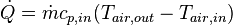
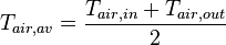
steady-state conditions, and Newton’s law of cooling to the temperature nodes shown in Figure 8 gives the following set of equations.
(1)
(2)
where
(3)
Using the mean air temperature is an assumption that is valid for relatively short heat sinks. When compact heat exchangers are calculated, the logarithmic mean air temperature is used. is the air mass flow rate in kg/s.
The above equations show that
When the air flow through the heat sink decreases, this results in an increase in the average air temperature. This in turn increases the heat sink base temperature. And additionally, the thermal resistance of the heat sink will also increase. The net result is a higher heat sink base temperature.
The increase in heat sink thermal resistance with decrease in flow rate will be shown later in this article.
The inlet air temperature relates strongly with the heat sink base temperature. For example, if there is recirculation of air in a product, the inlet air temperature is not the ambient air temperature. The inlet air temperature of the heat sink is therefore higher, which also results in a higher heat sink base temperature.
If there is no air flow around the heat sink, energy cannot be transferred.
A heat sink is not a device with the "magical ability to absorb heat like a sponge and send it off to a parallel universe".
Natural convection requires free flow of air over the heat sink. If fins are not aligned vertically, or if fins are too close together to allow sufficient air flow between them, the efficiency of the heat sink will decline
Heatsink Design
What characteristics make a heatsink a good one? There's a number of factors to consider:
High heatsink surface. It's at the surface of the heatsink where the thermal transfer takes place. Therefore, heatsinks should be designed to have a large surface; this goal can be reached by using a large amount of fine fins, or by increasing the size of the heatsink itself.
Good aerodynamics. Heatsinks must be designed in a way that air can easily and quickly float through the cooler, and reach all cooling fins. Especially heatsinks having a very large amount of fine fins, with small distances between the fins may not allow good air flow. A compromise between high surface (many fins with small gaps between them) and good aerodynamics must be found. This also depends on the fan the heatsink is used with: A powerful fan can force air even through a heatsink with lots of fine fins with only small gaps for air flow - whereas on a passive heatsink, there should be fewer cooling fins with more space between them. Therefore, simply adding a fan to a large heatsink designed for fanless usage doesn't necessarily result in a good cooler.
Good thermal transfer within the heatsink. Large cooling fins are pointless if the heat can't reach them, so the heatsink must be designed to allow good thermal transfer from the heat source to the fins. Thicker fins have better thermal conductivity; so again, a compromise between high surface (many thin fins) and good thermal transfer (thicker fins) must be found. Of course, the material used has a major influence on thermal transfer within the heatsink. Sometimes, heat pipes are used to lead the heat from the heat source to the parts of the fins that are further away from the heat source.
Perfect flatness of the contact area. The part of the heatsink that is in contact with the heat source must be perfectly flat. A flat contact area allows you to use a thinner layer of thermal compound, which will reduce the thermal resistance between heatsink and heat source.
For more detail on heat sink click the video down below.
3. DC BRUSHLESS FAN MOTOR
Figure 9: Example of brushless DC electric motor
Brushless DC electric motor (BLDC motors, BL motors) also known as electronically commutated motors (ECMs, EC motors) are synchronous motors that are powered by a DC electric source via an integrated inverter/switching power supply, which produces an AC electric signal to drive the motor. In this context, AC, alternating current, does not imply a sinusoidal waveform, but rather a bi-directional current with no restriction on waveform. Additional sensors and electronics control the inverter output amplitude and waveform (and therefore percent of DC bus usage/efficiency) and frequency (i.e. rotor speed).
The rotor part of a brushless motor is often a permanent magnet synchronous motor, but can also be a switched reluctance motor, or induction motor[citation needed].
Brushless motors may be described as stepper motors; however, the term stepper motor tends to be used for motors that are designed specifically to be operated in a mode where they are frequently stopped with the rotor in a defined angular position. This page describes more general brushless motor principles, though there is overlap.
Two key performance parameters of brushless DC motors are the motor constants Kv and Km
The video below will explain more on brushless DC electric motor.
Conclusion:
In conclusion, the heat sink with DC brushless motor fan are the important role of thermoelectric generator because they can create a constant temperature of cold side thermoelectric module and the voltage regulator are play important role to give a constant output (5V) but there are several problems which I will be facing:
How low temperature can be generate using heat sink with DC brushless motor fan at cold side thermoelectric module?
How much load current can be produced when applied voltage regulator?
DC-to-DC power converter is use in this project since the output of an thermoelectric module depends on the different temperature that generate on hot side and cold side, so the value output might be is smaller. By using with an output voltage greater than its input voltage means that the input voltage can be boost. DC-to-DC power converter It is a class of switched-mode power supply (SMPS) containing at least two semiconductor switches (a diode and a transistor) and at least one energy storage element, a capacitor, inductor, or the two in combination. Filters made of capacitors (sometimes in combination with inductors) are normally added to the output of the converter to reduce output voltage ripple. Power for the boost converter can come from any suitable DC sources, such as batteries, solar panels, rectifiers and DC generators. A process that changes one DC voltage to a different DC voltage is called DC to DC conversion. A boost converter is sometimes called a step-up converter since it “steps up” the source voltage. Since power (P=IV) must be conserved, the output current is lower than the source current.
In the video below will describe more detail the DC-DC Booster circuit.
Conclusion:
In conclusion, I need to step-up the voltage and current from thermoelectric module at least 5V, 100mA to USB port in case the output from thermoelectric module are too small but there are several problems which I will be facing:
How efficiency the DC-DC booster and how much the value of load current that can generate at output 5V?
How much that minimum input can be step-up to DC-DC booster circuit?
Attend for project proposal presentation briefing and take some important note.
Analysis/Procedure:
Today, I attend third fyp briefing at TTL hall. This briefing about the proposal presentation. The Speaker explained briefly and discussion about project proposal presentation. After the discussion and some advices, I manage to complete slide presentation as the following format:
1.Introduction
2.Problem Statement
3.Objectives.
4.Content of Presentation (including previous work, project methodology, materials and budget)
5.Progress of project (the operation, block diagram, flow chart, gantt chart, expected results and analysis)
6.The conclusion.
There is some important elements i should aware during the presentation:
1. Ability to handle questions.
2. The suitability of media chosen.
3.The interpersonal ability and communication skill.
4. Organization of presentation and time keeping.
Conclusion:
The briefing on presentaion is a great help for my presentation. I can prepare well and better to achieve satisfied mark on the presentation day.
Objective: To identify and research about the thermoelectric.
Analysis/Procedure:
The thermoelectric effect is the direct conversion of temperature differences to electric voltage and vice versa. The term "thermoelectric effect" encompasses three separately identified effects: the Seebeck effect, Peltier effect, and Thomson effect. Joule heating, the heat that is generated whenever a current is passed through a resistive material, is related though it is not generally termed a thermoelectric effect. A metal of unknown composition can be classified by its thermoelectric effect if a metallic probe of known composition is kept at a constant temperature and held in contact with the unknown sample that is locally heated to the probe temperature.
Figure 2: How thermoelectric module work
There is 2 type of thermoelectric module: 1. Thermoelectric Cooling (TEC) Module:
Figure 3: Thermoelectric Cooling (TEC) module
Thermoelectric cooling uses the Peltier effect to create a heat flux between the junction of two different types of materials. A Peltier cooler, heater, or thermoelectric heat pump is a solid-state active heat pump which transfers heat from one side of the device to the other, with consumption of electrical energy, depending on the direction of the current. Such an instrument is also called a Peltier device, Peltier heat pump, solid state refrigerator, or thermoelectric cooler (TEC). It can be used either for heating or for cooling,although in practice the main application is cooling. It can also be used as a temperature controller that either heats or cools.
2. Thermoelectric Generator (TEG) Module:
Figure 4: Thermoelectric Generator (TEG) module
Thermoelectric generators (also called Seebeck generators) are devices that convert heat (temperature differences) directly into electrical energy, using a phenomenon called the Seebeck effect (a form of thermoelectric effect).
The Seebeck effect is the conversion of temperature differences directly into electricity and is named after the Baltic German physicist Thomas Johann Seebeck. Seebeck, in 1821, discovered that a compass needle would be deflected by a closed loop formed by two different metals joined in two places, with a temperature difference between the junctions. This was because the metals responded to the temperature difference in different ways, creating a current loop and a magnetic field. Seebeck did not recognize there was an electric current involved, so he called the phenomenon the thermomagnetic effect. Danish physicist Hans Christian Ørsted rectified the mistake and coined the term "thermoelectricity".
In the video below will describe more detail the differences between Thermoelectric Cooling (TEC) module and Thermoelectric Generator (TEG) module.
Conclusion: In conclusion, Thermoelectric Generator (TEG) module has been chosen for this project but there are several problems which I will be facing:
How much voltage and current that i can get from Thermoelectric Generator (TEG)?
How to install properly the Thermoelectric Generator (TEG)?
Which range of temperature in between cold side and hot side that will gave best output voltage and current?


 , is proportional to the product of the temperature gradient and the cross-sectional area through which heat is transferred.
 (1)
(1) (2)
(2) (3)
(3) is the air mass flow rate in kg/s.